This amplifier provides two channels of power up to 20 watts RMS from two line inputs. Ideal for use in computers, because its price / power / complexity is optimal.
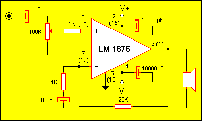
20w Stereo Amplifier Circuit Diagram
The drawing shows only one of the stages of the system since all circuit both stereo channels are exactly alike. Numbers in parentheses represents the equivalent of the terminal for the second channel. The heart of this project is a circuit from National Semiconductor , the LM1876 , which provides in pill two power operational amplifiers with mute function ( mute ) and standby ( off ) , which we have not implemented this design as an oversimplification .
The incoming signal , after being conditioned , level amplifier enters its non-inverting input . At the end of this part of the resulting signal is reinserted at its inverting amplifier to form the feedback network . Because the circuit is internally balanced when working with power starting not need to install the output capacitor BootStrap.en .
Assembly moduel.
Mounted integrated circuit.
POWER :
This system requires to operate a voltage of + / -28 Volts and a current of 2 amps. Can be used to obtain the classical source transformer , diode bridge and capacitors.
In this case the transformer should have a primary line to line voltage ( 220V) and secondary midpoint for each branch 20v ( 40v from end to end ) . The diodes should be 100V / 3A 1N5406 or equivalent type . Also usable bridge rectifier, which facilitates the task and reduces the number of tracks / space. The filter capacitors are 4700μF x 50v .
Picture of the power supply ( platelet )
HEAT SINK :
All key audio system , the heatsink that this time we use is a simple cooler for Pentium III computer . We use this model since it has a surface area greater than traditional metal . To power the vast fan with taking the positive phase of the source and lower your tension with a 7812 regulator dissipated individually.
Source Link: www.w3circuits.com
20w Stereo Amplifier Circuit Diagram
The drawing shows only one of the stages of the system since all circuit both stereo channels are exactly alike. Numbers in parentheses represents the equivalent of the terminal for the second channel. The heart of this project is a circuit from National Semiconductor , the LM1876 , which provides in pill two power operational amplifiers with mute function ( mute ) and standby ( off ) , which we have not implemented this design as an oversimplification .
The incoming signal , after being conditioned , level amplifier enters its non-inverting input . At the end of this part of the resulting signal is reinserted at its inverting amplifier to form the feedback network . Because the circuit is internally balanced when working with power starting not need to install the output capacitor BootStrap.en .
Assembly moduel.
Mounted integrated circuit.
POWER :
This system requires to operate a voltage of + / -28 Volts and a current of 2 amps. Can be used to obtain the classical source transformer , diode bridge and capacitors.
In this case the transformer should have a primary line to line voltage ( 220V) and secondary midpoint for each branch 20v ( 40v from end to end ) . The diodes should be 100V / 3A 1N5406 or equivalent type . Also usable bridge rectifier, which facilitates the task and reduces the number of tracks / space. The filter capacitors are 4700μF x 50v .
Picture of the power supply ( platelet )
HEAT SINK :
All key audio system , the heatsink that this time we use is a simple cooler for Pentium III computer . We use this model since it has a surface area greater than traditional metal . To power the vast fan with taking the positive phase of the source and lower your tension with a 7812 regulator dissipated individually.


Post a Comment